BS Pneumatic Weir-type Diaphragm Valve
manufacturer: Shanghai MeiYan Yi Pump & Valve Co., Ltd.
Eml: sales@1bengfa.com
Tel: +86 (21) 5640 2009
Mob: +86 138 1691 3072(WeChat Same Account)
product drawing

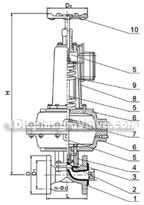
pneumatic rubber lined, fluorine lined diaphragm valves(pic1)

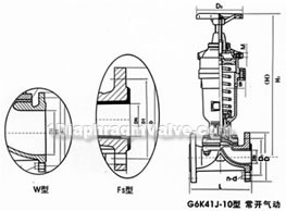
pneumatic rubber lined, fluorine lined diaphragm valve(pic2)
1.body 2.diaphragm 3.disc 4.bonnet 5.upper,middle,below stem 6.cylinder 7.pneumatic diaphragm 8.spring gland 9.spring 10.handwheel
The materials of main parts
| part name | body | disc, bonnet | cylinder, cylinder cover | diaphragm | screw,stem,piston |
| materials | HT200 fluorine plastic, rubber lined | HT200 | HT200 | Fluorine-polybutadiene rubber, fluorine plastic | 35 |
External and connection dimensions and weight

pneumatic rubber lined, fluorine lined diaphragm valve constructral diagram

EG6K41J-(normally closed) constructral diagram
| model | nominal diameter DN (mm) |
dimensions (mm) | pneumatic devices | weight ㎏ |
|||||||||||||||||
| L | f | D1 | D | Do | n-d | H | B | code ES |
gas consumption Cn3 |
air supply pressure MPa |
air supply connector in |
||||||||||
| J type |
W type |
||||||||||||||||||||
| EG6K41W/J/FS-16 | 20 | 121 | 117 | 2 | 75 | 105 | 140 | 4-13.5 | 343 | 168 | 68 | 163.87 | 0.3 | 1/8 | 6.3 | ||||||
| 25 | 131 | 127 | 2 | 85 | 115 | 140 | 4-13.5 | 345 | 168 | 68 | 196.65 | 0.3~0.4 | 1/8 | 7.3 | |||||||
| 32 | 150 | 146 | 2 | 100 | 140 | 140 | 4-17.5 | 363 | 260 | 68 | 229.4 | 0.3~0.4 | 1/8 | 8.3 | |||||||
| 40 | 163 | 159 | 2 | 110 | 150 | 140 | 4-17.5 | 430 | 260 | 69 | 1458.7 | 0.3~0.4 | 1/4 | 14.5 | |||||||
| 50 | 194 | 190 | 2 | 125 | 165 | 140 | 4-17.5 | 575 | 260 | 70 | 3162.7 | 0.3~0.4 | 1/4 | 26 | |||||||
| EG6K41W/J/FS-10 | 65 | 220 | 216 | 2 | 145 | 185 | 140 | 4-17.5 | 588 | 260 | 70 | 3243 | 0.3~0.4 | 1/4 | 30.8 | ||||||
| 80 | 258 | 254 | 2 | 160 | 200 | 165 | 8-17.5 | 769 | 425 | 71 | 6636.8 | 0.4~0.5 | 3/8 | 64.9 | |||||||
| 100 | 309 | 305 | 2 | 180 | 220 | 280 | 8-17.5 | 816 | 425 | 71 | 6948 | 0.4~0.5 | 3/8 | 70.3 | |||||||
| 125 | 362 | 356 | 3 | 210 | 250 | 280 | 8-17.5 | 820 | 425 | 71 | 7374.2 | 0.4~0.5 | 3/8 | 80.7 | |||||||
| 150 | 412 | 406 | 3 | 240 | 285 | 280 | 8-22 | 920 | 549 | 72 | 10652 | 0.5 | 3/8 | ||||||||
| EG6K41W.J.FS-6 | 200 | 527 | 521 | 4 | 295 | 340 | 280 | 8-22 | 1010 | 549 | 72 | 16715 | 0.6 | 3/8 | 212 | ||||||
| EG6K41W/J/FS-16 | 20 | 121 | 117 | 2 | 75 | 105 | 120 | 4-13.5 | 168 | 61 | 163.87 | 0.3 | 1/8 | 7.2 | |||||||
| 25 | 131 | 127 | 2 | 85 | 115 | 120 | 4-13.5 | 394 | 168 | 61 | 196.65 | 0.3~0.4 | 1/8 | 8.9 | |||||||
| 32 | 150 | 146 | 2 | 100 | 140 | 120 | 4-17.5 | 400 | 168 | 61 | 229.4 | 0.3~0.4 | 1/8 | 10.6 | |||||||
| 40 | 163 | 159 | 2 | 110 | 150 | 165 | 4-17.5 | 485 | 260 | 62 | 1425.7 | 0.3~0.4 | 1/4 | 19.5 | |||||||
| 50 | 194 | 190 | 2 | 125 | 165 | 165 | 4-17.5 | 635 | 318 | 63 | 2284.1 | 0.3~0.4 | 1/4 | 34.9 | |||||||
| EG6K41W/J/FS-10 | 65 | 220 | 216 | 2 | 145 | 185 | 165 | 4-17.5 | 650 | 318 | 63 | 3048 | 0.3~0.4 | 1/4 | 39.9 | ||||||
| 80 | 258 | 254 | 2 | 160 | 200 | 165 | 8-17.5 | 660 | 318 | 63 | 3244.7 | 0.4~0.5 | 3/8 | 51.9 | |||||||
| 100 | 309 | 305 | 2 | 180 | 220 | 280 | 8-17.5 | 816 | 425 | 64 | 6964.7 | 0.4~0.5 | 3/8 | 93.2 | |||||||
| 125 | 362 | 356 | 3 | 210 | 250 | 280 | 8-17.5 | 825 | 425 | 64 | 7439.7 | 0.4~0.5 | 3/8 | 105.3 | |||||||
| 150 | 412 | 406 | 3 | 240 | 285 | 310 | 8-22 | 1013 | 549 | 65 | 14912 | 0.5 | 3/8 | 184.5 | |||||||
| EG6K41W.J.FS-6 | 200 | 529 | 521 | 4 | 295 | 340 | 483 | 8-22 | 1300 | 749 | 65 | 49161 | 0.6 | 1/2 | 407.4 | ||||||
1、design and manufacture according to:GB12239 or BS5156
2、face to face dimension according to:GB12221 or BS5156
3、flange connection dimension according to:GB4216.4 or BS4504
4、test and inspection according to:GB/T13927 or BS5156


