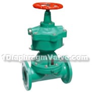
Reciprocating-type Pneumatic Diaphragm Valve
manufacturer: Shanghai MeiYan Yi Pump & Valve Co., Ltd.
Eml: sales@1bengfa.com
Tel: +86 (21) 5640 2009
Mob: +86 138 1691 3072(WeChat Same Account)
product drawing

G641W/J/Fs-6 type reciprocating-type pneumatic diaphragm valves, reciprocating-type fluorine lined pneumatic diaphragm valves
Main performance and specifications
| working temperature | applicable medium |
| ≤85℃ | J:general corrosive medium |
| ≤120℃ | FS:strong corrosive medium |
Note: This is our company based-type products suitable temperature, if you have different requirement, please refer to the previous page shows for selection.
The materials of main parts
body:cast iron, cast iron/rubber lined, fluorine plastic bonnet: cast iron cylinder cover:cast iron film: natural rubber screw: carbon steel screw sleeve: carbon steel disc: cast iron handwheel:cast iron diaphragm: Natural rubber, butyl rubber, fluorine paint / rubber stem:carbon steel
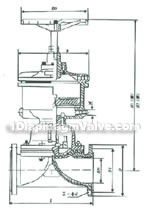
Main externaland connection dimensions

G641W/J/Fs-6 type reciprocating-type pneumatic diaphragm valve, reciprocating-type fluorine lined pneumatic diaphragm valve constructral diagram
| nominal diameter | nominal pressure /MPa |
working pressure /Mpa |
L | D | D1 | Z-d | H1 | H2 | Do | B | pneumatic device parameter | weight /㎏ |
|||
| DN /mm |
NPS/inc h |
air supply pressure /MPa |
air supply connector /m |
gas consumption /cm2 |
|||||||||||
| 25 | 1 | 0.6 | 0.6 | 145 | 115 | 85 | 4-14 | 250 | 264 | 120 | 94 | 0.4 | 10×1 | 2.395×10² | 6.5 |
| 32 | 1 1/4 | 160 | 135 | 100 | 4-18 | 140 | 120 | 0.4 | 12×1.25 | 6.082×10² | |||||
| 40 | 1 1/2 | 180 | 145 | 110 | 4-18 | 140 | 120 | 0.4 | 12×1.25 | 6.082×10² | |||||
| 50 | 2 | 210 | 160 | 125 | 4-18 | 379 | 405 | 160 | 182 | 0.4 | 12×1.25 | 1.235×10³ | 25 | ||
| 65 | 2 1/2 | 250 | 180 | 145 | 4-18 | 0.4 | 16×1.5 | 31.5 | |||||||
| 80 | 3 | 300 | 195 | 160 | 4-18 | 183 | 523 | 240 | 245 | 0.5 | 16×1.5 | 3.725×10³ | 62.5 | ||
| 100 | 4 | 350 | 215 | 180 | 8-18 | 565 | 617 | 280 | 330 | 0.5 | 16×1.5 | 9.458×10³ | 93.5 | ||
| 125 | 5 | 400 | 245 | 210 | 8-18 | 664 | 732 | 320 | 380 | 0.5 | 20×1.5 | 1.409×10⁴ | 114 | ||
| 150 | 6 | 460 | 280 | 240 | 8-22 | 750 | 830 | 320 | 470 | 0.5 | 20×1.5 | 2.868×10⁴ | 164 | ||
| 200 | 8 | 0.4 | 570 | 335 | 295 | 8-22 | 930 | 1050 | 400 | 470 | 0.5 | 20×1.5 | 4.619×10⁴ | 249 | |
| nominal diameter | nominal pressure /MPa |
working pressure /Mpa |
L | D | D1 | Z-d | H1 | H2 | Do | B | pneumatic device parameter | weight /㎏ |
|||
| DN /mm |
NPS/inc h |
air supply pressure /MPa |
air supply connector /m |
gas consumption /cm2 |
|||||||||||
| 25 | 1 | 0.6 | 0.6 | 145 | 115 | 85 | 4-14 | 250 | 264 | 120 | 94 | 0.4 | 10×1 | 2.395×10² | 6.5 |
| 32 | 1 1/4 | 160 | 135 | 100 | 4-18 | 140 | 120 | 0.4 | 12×1.25 | 6.082×10² | |||||
| 40 | 1 1/2 | 180 | 145 | 110 | 4-18 | 140 | 120 | 0.4 | 12×1.25 | 6.082×10² | |||||
| 50 | 2 | 210 | 160 | 125 | 4-18 | 379 | 405 | 160 | 223 | 0.4 | 12×1.25 | 2.467×10² | 25 | ||
| 65 | 2 1/2 | 250 | 180 | 145 | 4-18 | 0.4 | 31.5 | ||||||||
| 80 | 3 | 300 | 195 | 160 | 4-18 | 183 | 523 | 240 | 330 | 0.5 | 16×1.5 | 8.759×10² | 63.5 | ||
| 100 | 4 | 350 | 215 | 180 | 8-18 | 565 | 617 | 280 | 380 | 0.5 | 20×1.5 | 1.609×10² | 93.5 | ||
| 125 | 5 | 400 | 245 | 210 | 8-18 | 668 | 734 | 320 | 440 | 0.5 | 20×1.5 | 2.055×10² | 125 | ||
| 150 | 6 | 460 | 280 | 240 | 8-22 | 771 | 851 | 320 | 515 | 0.5 | 20×1.5 | 4.873×10² | 213.5 | ||
| 200 | 8 | 570 | 335 | 295 | 8-22 | 968 | 1078 | 500 | 620 | 0.5 | 30×2 | 1.232×10² | 248.5 | ||
implement standard design and manufacture:GB12239 face to face dimension:GB11688 flange connection dimension:JB78(PN1.0MPa)


